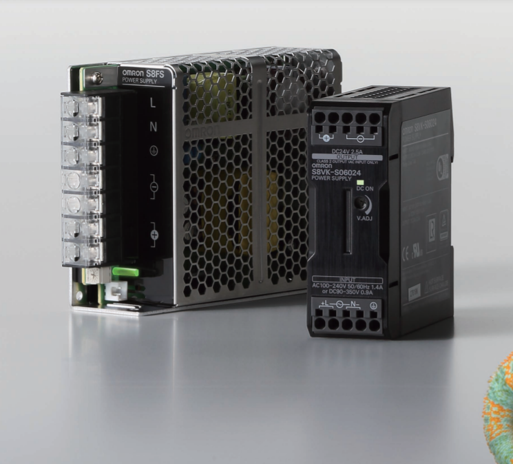
Power Supplies That Are Ideal for Machine Tools and Semiconductor Manufacturing Equipment
No Transformers Required for Control Circuits
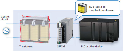
Built-in IEC 61558-2-16 Compliant Transformer
An IEC 61558-2-16 compliant transformer is built into the Power Supply to eliminate the need for a transformer with compound windings for control circuits for which IEC 60204-1 Machinery Directive is specified. This helps reduce cost and space requirements.
Easy Safety Standard Certification
All Normal Stock Models Are UL 508 Listed *
1. Less work is required to prepare data and materials for UL application.
2. Connection is possible to devices or equipment outside the control panel.
* Some optional models are UL recognized. (Excluding models with connectors.)
2. Connection is possible to devices or equipment outside the control panel.
* Some optional models are UL recognized. (Excluding models with connectors.)

Equipment Downsizing
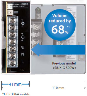
Slim Body of 300-/600-W models
Stable Operation in a Wide Range of Environments
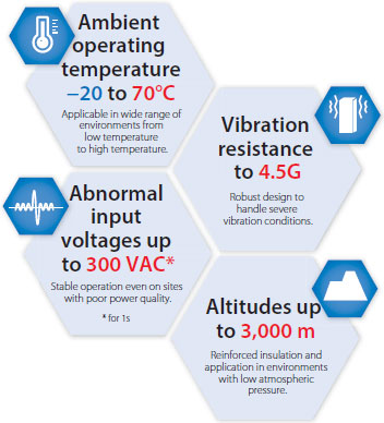
Resistance to Environments for Global Application
Stable operation in severe installation environments, such as those with high ambient temperatures and humidity, or large vibration or those with unstable input voltages.
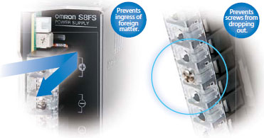
Prevention of Foreign Matter Ingress and Screw Drop Out
The front cover prevents entry of foreign matter from the front surface.
A removable mechanism that prevents terminal block screws from dropping out is a standard feature.
A removable mechanism that prevents terminal block screws from dropping out is a standard feature.
You can prevent foreign matter ingress and screw drop out that can result in product failure and accidents for worry-free installation and maintenance work.
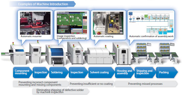
Stable, High Quality
75% of all the manufacturing processes have been mechanized.
We have also mechanized inspection and confirmation processes.
We have also mechanized inspection and confirmation processes.
Specification
| Power rating | 15 W | |||||
|---|---|---|---|---|---|---|
| Output voltage (VDC) | 5 V | 12 V | 15 V | 24 V | ||
| Efficiency * | 100 VAC input | 80% typ. | 84% typ. | 84% typ. | 85% typ. | |
| 200 VAC input | 80% typ. | 84% typ. | 84% typ. | 86% typ. | ||
| 230 VAC input | 80% typ. | 84% typ. | 84% typ. | 86% typ. | ||
| Input | Voltage range * | Single phase, 85 to 264 VAC, 80 to 370 VDC | ||||
| Frequency * | 50/60 Hz (47 to 450 Hz) | |||||
| Current * | 100 VAC input | 0.32 A typ. | ||||
| 200 VAC input | 0.2 A typ. | |||||
| Power factor * | — | |||||
| Leakage current * |
100 VAC input | 0.5 mA max. | ||||
| 200 VAC input | 1 mA max. | |||||
| Inrush current * (for a cold start at 25°C) |
100 VAC input | 14 A typ. | ||||
| 200 VAC input | 28 A typ. | |||||
| Output | Rated Output Current | 3 A | 1.3 A | 1 A | 0.65 A | |
| Voltage adjustment range * | -10% to 15% (with V.ADJ) | |||||
| Ripple & Noise voltage * |
100 to 240 VAC input |
40 mVp-p max. | 40 mVp-p max. | 40 mVp-p max. | 60 mVp-p max. | |
| Input variation influence * | 0.5% max. | |||||
| Load variation influence * | 1.0% max. | |||||
| Temperature variation influence |
100 to 240 VAC input |
0.05%/°C max. | ||||
| Startup time * | 100 VAC input | 1,000 ms max. | ||||
| 200 VAC input | 1,000 ms max. | |||||
| Hold time * | 100 VAC input | 15 ms typ. | 14 ms typ. | 15 ms typ. | 15 ms typ. | |
| 200 VAC input | 75 ms typ. | 70 ms typ. | 75 ms typ. | 70 ms typ. | ||
| Additional functions |
Overload protection | Yes, automatic reset | ||||
| Overvoltage protection * | Yes, 120% or higher of rated output voltage, power shut off (shut off the input voltage and turn on the input again) |
|||||
| Overheat protection | No | |||||
| Series operation | Yes (For up to two Power Supplies, external diodes are required.) | |||||
| Parallel operation | No (However, backup operation is possible, external diodes are required.) | |||||
| Remote sensing | No | |||||
| Remote control | No | |||||
| Output indicator | Yes (LED: Green) | |||||
| Insulation | Withstand voltage | 3 kVAC for 1 min. (between all input terminals and output terminals) current cutoff 20 mA |
||||
| 2 kVAC for 1 min. (between all input terminals and PE terminals) current cutoff 20 mA |
||||||
| 1 kVAC for 1 min. (between all output terminals and PE terminals) current cutoff 20 mA |
||||||
| Insulation resistance | 100 MΩ min. (between all output terminals and all input terminals/PE terminals) at 500 VDC |
|||||
| Environ- ment |
Ambient operating temperature |
-20 to 70°C (Derating is required according to the temperature.) (with no condensation or icing) |
||||
| Storage temperature | -25 to 75°C (with no condensation or icing) | |||||
| Ambient operating humidity | 90% max. (Storage humidity: 90% max.) | |||||
| Vibration resistance | 10 to 55 Hz, 4.5 G max., 0.375-mm half amplitude for 2 h each in X, Y, and Z directions |
|||||
| Shock resistance | 150 m/s2, 3 times each in ±X, ±Y, ±Z directions | |||||
| Reliability | MTBF | 135,000 hrs min. | ||||
| Life expectancy * | 10 years min. | |||||
| Con- struction |
Dimensions (W×H×D) | Refer to Dimensions. | ||||
| Weight | 250 g | |||||
| Cooling fan | No | |||||
| Degree of protection | — | |||||
| Standards | Harmonic current emissions | Conforms to EN 61000-3-2 | ||||
| EMI * | Conducted Emissions |
Conforms to EN 61204-3 Class B, EN 55011 Class B | ||||
| Radiated Emissions |
Conforms to EN 61204-3 Class B, EN 55011 Class B | |||||
| EMS | Conforms to EN 61204-3 high severity levels | |||||
| Safety Standards | UL 508 (Listing, excluding models with connector option) UL 62368-1 (Recognition, OVCII [≤ 3,000 m], Pol2) CSA C22.2 No.107.1 (excluding models with connector option) CSA C22.2 No.62368-1 (excluding models with connector option) EN 50178 (OVCIII [≤ 2,000 m], OVCII [> 2,000 m and ≤ 3,000 m], Pol2) EN/IEC 62368-1 (OVCII [≤ 3,000 m], Pol2) Conforms to EN/IEC 61558-2-16 Conforms to PELV (EN/IEC 60204-1) EAC (TR CU 004/2011, TR CU 020/2011) RCM (EN61000-6-4) |
|||||
| Marine Standards | No | |||||
| SEMI | Conforms to F47-0706 (200 VAC input) | |||||
Order Code
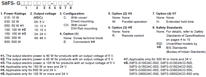
Model List
| ower ratings | Input voltage | Output voltage (VDC) | Output current | Built-in fan | Model |
|---|---|---|---|---|---|
| 15 W | 100 to 240 VAC (Permissible range 85 to 264 VAC, 80 to 370 VDC) *4 |
5 V | 3 A | None | S8FS-G01505CD |
| 12 V | 1.3 A | S8FS-G01512CD | |||
| 15 V | 1 A | S8FS-G01515CD | |||
| 24 V | 0.65 A | S8FS-G01524CD | |||
| 30 W | 5 V | 6 A | S8FS-G03005CD | ||
| 12 V | 3 A | S8FS-G03012CD | |||
| 15 V | 2.4 A | S8FS-G03015CD | |||
| 24 V | 1.5 A | S8FS-G03024CD | |||
| 50 W | 5 V | 8 A *1 | S8FS-G05005CD | ||
| 12 V | 4.3 A | S8FS-G05012CD | |||
| 15 V | 3.5 A | S8FS-G05015CD | |||
| 24 V | 2.2 A | S8FS-G05024CD | |||
| 100 W | 5 V | 16 A *2 | S8FS-G10005CD | ||
| 12 V | 8.5 A | S8FS-G10012CD | |||
| 15 V | 7 A | S8FS-G10015CD | |||
| 24 V | 4.5 A | S8FS-G10024CD | |||
| 150 W | 5 V | 21 A *3 | S8FS-G15005CD | ||
| 12 V | 13 A | S8FS-G15012CD | |||
| 15 V | 10 A | S8FS-G15015CD | |||
| 24 V | 6.5 A | S8FS-G15024CD | |||
| 48 V | 3.3 A | S8FS-G15048CD | |||
| 300 W | 100 to 240 VAC (Permissible range 85 to 264 VAC, 120 to 370 VDC) |
12 V | 25 A | Yes | S8FS-G30012CD |
| 15 V | 20 A | S8FS-G30015CD | |||
| 24 V | 14 A | S8FS-G30024CD | |||
| 48 V | 7 A | S8FS-G30048CD | |||
| 600 W | 100 to 240 VAC (Permissible range 85 to 264 VAC, 120 to 350 VDC) |
12 V | 50 A | S8FS-G60012CD | |
| 15 V | 40 A | S8FS-G60015CD | |||
| 24 V | 27 A | S8FS-G60024CD | |||
| 48 V | 13 A | S8FS-G60048CD |


