
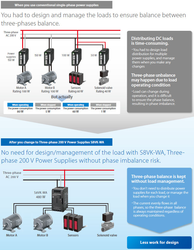
Complex designing with single-phase power supplies is no longer necessary
Three-phase 200 V Power Supplies diminish the risk of three-phase imbalance.
Full of functions for higher design efficiency
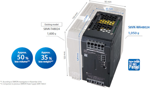
Compact body allows easy replacement.
World’s smallest class of compact body *1
This high-capacity yet compact Power Supply requires only less than half the space of the existing models.
Side-by-side mounting possible.

Our shared Value Design for Panel concept for the specifi cations of products used in control panels will create new value to our customer’s control panels.
Combining multiple products that share the Value Design concept will further increase the value provided to control panels.
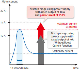
The peak current (150% to the rated current) solves the issue of momentary surge of current to motor load.
Motor-driven devices such as electric cylinders carry maximal instantaneous current when they start.
When the maximum current exceeds the rated current of a power supply without Boost Current Function, overload protection is activated to limit the output current. To avoid this, you must select a power supply with a rated output larger than the maximum current.
For example, if the maximum current exceeds 10 A, as in the figure on the below, you need a power supply with a rated output of 20 A.
S8VK-WA is equipped with a Boost Current Function that allows a peak current (150% of rated output) to flow for 10 seconds, which ensures a stable startup by a power supply with a rated output current of 10 A as described in the figure on the below.
S8VK-WA solves maintenance issues
Support for efficient maintenance and quick rec overy from errors.
Have you ever had these issues in maintaining power supplies?
The equipment stopped and no output from the power supply.
Disconnecting cables and inspection with a tester is required to identify the cause, taking time and work.
Problems
・The cause is not clear.
・The failure cannot be reproduced.
・The problem recurs even after the power supply is replaced.
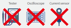
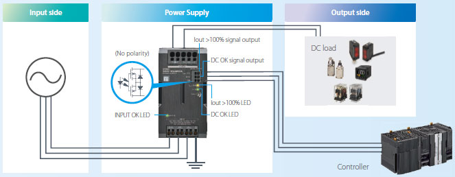
Built-in maintenance point indicator indicates where to start
S8VK-WA shows you the source of the problem (e.g. input/output side of the Power Supply, or the main body),
without disconnecting cables or using a tester.
LED and signal output indicates the status of the Power Supply.
When the door of the control panel is closed, you can still check the status of the Power Supply via your controller, etc.,
using the signal that is output in synchronization with the LED
This feature clarifies the error status and necessary maintenance, minimizing the downtime.
Frequent causes of output fall
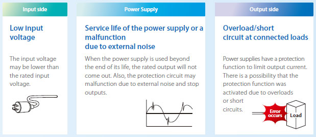
LED/signal output patterns and required maintenance
Function of LED/signal
INPUT OK LED: Lights up when the input voltage exceeds the lower limit value of the permissible range.
DC OK LED/signal: Lights up/Signal Output , when the output voltage is more than 90% of the rated output voltage.
Iout >100% LED/signal: Lights up/Signal Output , when the output current exceeds the rated output current.
Specification
Ratings, Characteristics, and Functions
| Power rating | 240 W | 480 W | 960 W | ||
|---|---|---|---|---|---|
| Output voltage (VDC) | 24 V | 24 V | 24 V | ||
| Efficiency *1 | Three-phase 200 VAC input |
93% typ. | 94% typ. | 95% typ. | |
| Single-phase 200 VAC input |
92% typ. | 93% typ. | 94% typ. | ||
| Three-phase 230 VAC input |
93% typ. | 94% typ. | 95% typ. | ||
| Single-phase 230 VAC input |
93% typ. | 94% typ. | 95% typ. | ||
| Input con- ditions |
Input voltage range *2 | Three-phase/single-phase 170 to 264 VAC, 265 to 300 VAC (1 second) 240 to 350 VDC |
|||
| Frequency *2 | 50/60 Hz (47 to 63 Hz) | ||||
| Input current *1 |
Three-phase 200 VAC input |
0.80 A typ. | 1.6 A typ. | 3.1 A typ. | |
| Single-phase 200 VAC input |
1.4 A typ. | 2.6 A typ. | 5.2 A typ. | ||
| Three-phase 230 VAC input |
0.70 A typ. | 1.4 A typ. | 2.7 A typ. | ||
| Single-phase 230 VAC input |
1.2 A typ. | 2.3 A typ. | 4.5 A typ. | ||
| Power factor *1 | 0.9 min. | ||||
| Leakage current *3 |
Three-phase 200 VAC input |
1 mA max. | |||
| Three-phase 230 VAC input |
1 mA max. | ||||
| Inrush current *4 (for a cold start at 25°C) |
Three-phase 200 VAC input |
13 A typ. | 13 A typ. | 14 A typ. | |
| Three-phase 230 VAC input |
15 A typ. | 15 A typ. | 16 A typ. | ||
| Output character- istics |
Rated output current | 10 A | 20 A | 40 A | |
| Power Boost Function | 15 A | 30 A | 60 A | ||
| Voltage adjustment range *5 | 24 to 29.5 V (with V.ADJ) | 24 to 28 V (with V.ADJ) | |||
| Ripple noise voltage *6 |
Three-phase 200 to 240 VAC input |
50 mVp-p max. at 20 MHz of bandwidth |
120 mVp-p max. at 20 MHz of bandwidth |
60 mVp-p max. at 20 MHz of bandwidth |
|
| Input variation influence *7 | 0.5% max. | ||||
| Load variation influence *8 | 1.5% max. | ||||
| Temperature variation influence |
200 to 240 VAC input |
0.05%/°C max. | |||
| Startup time *9 |
Three-phase 200 VAC input |
1,000 ms max. | |||
| Three-phase 230 VAC input |
1,000 ms max. | ||||
| Output hold time *9 |
Three-phase 200 VAC input |
35 ms typ. | 30 ms typ. | 25 ms typ. | |
| Three-phase 230 VAC input |
35 ms typ. | 30 ms typ. | 25 ms typ. | ||
| Additional functions |
Overload protection | Yes, automatic reset, intermittent operation type Refer to Overload Protection below. |
|||
| Overvoltage protection | Yes, 130% or higher of rated output voltage, power shut off (shut off the input voltage and turn on the input again), Refer to Overvoltage Protection below. |
||||
| Series operation | Yes (For up to two Power Supplies; external diodes required.) | ||||
| Parallel operation | Yes (For up to two Power Supplies), Refer to Parallel Operation on Data sheet. |
||||
| INPUT OK Indicator | Yes (LED: Green) | ||||
| DC OK Indicator | Yes (LED: Green) | ||||
| Iout > 100% Indicator | Yes (LED: Yellow) | ||||
| DC OK Signal Output | Yes (MOS FET relay output 30 VDC max., 50 mA max.) | ||||
| Iout > 100% signal output | Yes (MOS FET relay output 30 VDC max., 50 mA max.) | ||||
| Insulation | Withstand voltage | 3.0 kVAC for 1 min. (between all input terminals and all output terminals, signal output terminals), cutoff current 20 mA |
|||
| 2.0 kVAC for 1 min. (between all input terminals and PE terminals), cutoff current 20 mA |
|||||
| 1.0 kVAC for 1 min. (between all output terminals, signal output terminals and PE terminals), cutoff current 25 mA |
|||||
| 0.5 kVAC for 1 min. (between all output terminals and all signal output terminals), cutoff current 10 mA |
|||||
| Insulation resistance | 100 MΩ min. (between all output terminals, signal output terminals and all input terminals / PE terminals) at 500 VDC |
||||
| Environ- ment |
Ambient operating temperature *10 |
-40 to 70°C (Derating is required according to the temperature. Refer to Engineering Data on Data sheet.) (with no condensation or icing) |
|||
| Storage temperature | -40 to 85°C (with no condensation or icing) | ||||
| Ambient operating humidity | 95% max. (Storage humidity: 95% max.) | ||||
| Vibration resistance | 10 to 55 Hz, maximum 5 G, 0.42 mm single amplitude for 2 h each in X, Y, and Z directions |
||||
| Shock resistance | 294 m/s2, 3 times each in ±X, ±Y, ±Z directions | ||||
| Reliability | MTBF *11 | 290,000 hrs typ. | 230,000 hrs typ. | 170,000 hrs typ | |
| Expected life *12 | 10 years min. | ||||
| Construc- tion |
Weight | 800 g max. | 1,050 g max. | 1,750 g max. | |
| Cooling fan | No | ||||
| Degree of protection | IP20 by EN/IEC 60529 | ||||
| Standards | Harmonic current emissions | Conforms to EN 61000-3-2 (single-phase *13) Complies with JIS C 61000-3-2 (three-phase, single-phase) |
|||
| EMI | Conducted emissions |
Conforms to EN 61204-3 Class B, EN 55011 Class B (three-phase) Conforms to EN 61204-3 Class A, EN 55011 Class A (single-phase) |
Conforms to EN 61204-3 Class B, EN 55011 Class B (three-phase) Conforms to EN 61204-3 Class B, EN 55011 Class B (single-phase *14) Conforms to EN 61204-3 Class A, EN 55011 Class A (single-phase) |
||
| Radiated emissions |
|||||
| EMS | Conforms to EN 61204-3 high severity levels | ||||
| Safety standards | UL 508 (Listing) CSA C22.2 No.107.1 (cUL) UL 62368-1 (Recognition) OVC II (≤ 3000 m) Pol2 CSA C22.2 No.62368-1 (cUR) OVC II (≤ 3000 m) Pol2 EN/IEC 62477-1 OVC III (≤ 2000 m) OVC II (2000 m < and ≤ 3000 m) Pol2 EN/IEC 62368-1 OVC II (≤ 3000 m) Pol2 EAC (TR CU 004 / 2011, TR CU 020 / 2011) RCM (EN61000-6-4) Complies with PELV (EN/IEC 60204-1) Complies with EN/IEC 61558-2-16 |
||||
| SEMI | Complies with SEMI F47-0706 (three-phase / single-phase 200 to 240 VAC input) |
||||