INTRODUCTION TO SAFETY VALVES
Any pressurised system requires safety devices to protect people, processes and property. This tutorial details situations when overpressure may occur, the wide and often confusing types of device on offer, how such devices operate and the many codes, standards and approval authorities to note.
Contents [hide]
Introduction to Safety Valves
As soon as mankind was able to boil water to create steam, the necessity of the safety device became evident. As long as 2000 years ago, the Chinese were using cauldrons with hinged lids to allow (relatively) safer production of steam. At the beginning of the 14th century, chemists used conical plugs and later, compressed springs to act as safety devices on pressurised vessels.
Early in the 19th century, boiler explosions on ships and locomotives frequently resulted from faulty safety devices, which led to the development of the first safety relief valves.
In 1848, Charles Retchie invented the accumulation chamber, which increases the compression surface within the safety valve allowing it to open rapidly within a narrow overpressure margin.
Today, most steam users are compelled by local health and safety regulations to ensure that their plant and processes incorporate safety devices and precautions, which ensure that dangerous conditions are prevented.
The primary function of a safety valve is therefore to protect life and property.
The principle type of device used to prevent overpressure in plant is the safety or safety relief valve. The safety valve operates by releasing a volume of fluid from within the plant when a predetermined maximum pressure is reached, thereby reducing the excess pressure in a safe manner. As the safety valve may be the only remaining device to prevent catastrophic failure under overpressure conditions, it is important that any such device is capable of operating at all times and under all possible conditions.
Safety valves should be installed wherever the maximum allowable working pressure (MAWP) of a system or pressure-containing vessel is likely to be exceeded. In steam systems, safety valves are typically used for boiler overpressure protection and other applications such as downstream of pressure reducing controls. Although their primary role is for safety, safety valves are also used in process operations to prevent product damage due to excess pressure. Pressure excess can be generated in a number of different situations, including:
- An imbalance of fluid flowrate caused by inadvertently closed or opened isolation valves on a process vessel.
- Failure of a cooling system, which allows vapour or fluid to expand.
- Compressed air or electrical power failure to control instrumentation.
- Transient pressure surges.
- Exposure to plant fires.
- Heat exchanger tube failure.
- Uncontrollable exothermic reactions in chemical plants.
- Ambient temperature changes.
The terms ‘safety valve’ and ‘safety relief valve’ are generic terms to describe many varieties of pressure relief devices that are designed to prevent excessive internal fluid pressure build-up. A wide range of different valves is available for many different applications and performance criteria.
Furthermore, different designs are required to meet the numerous national standards that govern the use of safety valves.
A listing of the relevant national standards can be found at the end of this module.
In most national standards, specific definitions are given for the terms associated with safety and safety relief valves. There are several notable differences between the terminology used in the USA and Europe. One of the most important differences is that a valve referred to as a ‘safety valve’ in Europe is referred to as a ‘safety relief valve’ or ‘pressure relief valve’ in the USA. In addition, the term ‘safety valve’ in the USA generally refers specifically to the full-lift type of safety valve used in Europe.
The ASME/ANSI PTC25.3 standards applicable to the USA define the following generic terms:
- Pressure relief valve – A spring-loaded pressure relief valve which is designed to open to relieve excess pressure and to reclose and prevent the further flow of fluid after normal conditions have been restored. It is characterised by a rapid-opening ‘pop’ action or by opening in a manner generally proportional to the increase in pressure over the opening pressure. It may be used for either compressible or incompressible fluids, depending on design, adjustment, or application.
This is a general term, which includes safety valves, relief valves and safety relief valves.
- Safety valve – A pressure relief valve actuated by inlet static pressure and characterised by rapid opening or pop action.
Safety valves are primarily used with compressible gases and in particular for steam and air services. However, they can also be used for process type applications where they may be needed to protect the plant or to prevent spoilage of the product being processed.
- Relief valve – A pressure relief device actuated by inlet static pressure having a gradual lift generally proportional to the increase in pressure over opening pressure.
Relief valves are commonly used in liquid systems, especially for lower capacities and thermal expansion duty. They can also be used on pumped systems as pressure overspill devices.
- Safety relief valve – A pressure relief valve characterised by rapid opening or pop action, or by opening in proportion to the increase in pressure over the opening pressure, depending on the application, and which may be used either for liquid or compressible fluid.
In general, the safety relief valve will perform as a safety valve when used in a compressible gas system, but it will open in proportion to the overpressure when used in liquid systems, as would a relief valve.
The European standard EN ISO 4126-1 provides the following definition:
- Safety valve – A valve which automatically, without the assistance of any energy other than that of the fluid concerned, discharges a quantity of the fluid so as to prevent a predetermined safe pressure being exceeded, and which is designed to re-close and prevent further flow of fluid after normal pressure conditions of service have been restored.
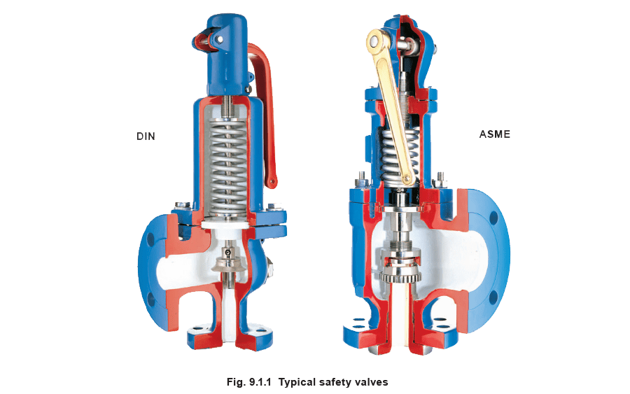
Typical examples of safety valves used on steam systems are shown in Figure 9.1.1.
Safety valve design
The basic spring loaded safety valve, referred to as ‘standard’ or ‘conventional’ is a simple, reliable self-acting device that provides overpressure protection.
The basic elements of the design consist of a right angle pattern valve body with the valve inlet connection, or nozzle, mounted on the pressure-containing system. The outlet connection may be screwed or flanged for connection to a piped discharge system. However, in some applications, such as compressed air systems, the safety valve will not have an outlet connection, and the fluid is vented directly to the atmosphere.

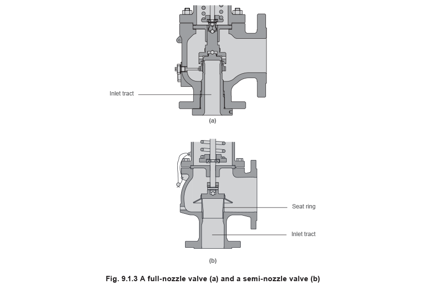
The valve inlet (or approach channel) design can be either a full-nozzle or a semi-nozzle type. A full-nozzle design has the entire ‘wetted’ inlet tract formed from one piece. The approach channel is the only part of the safety valve that is exposed to the process fluid during normal operation, other than the disc, unless the valve is discharging.
Full-nozzles are usually incorporated in safety valves designed for process and high pressure applications, especially when the fluid is corrosive.
Conversely, the semi-nozzle design consists of a seating ring fitted into the body, the top of which forms the seat of the valve. The advantage of this arrangement is that the seat can easily be replaced, without replacing the whole inlet.
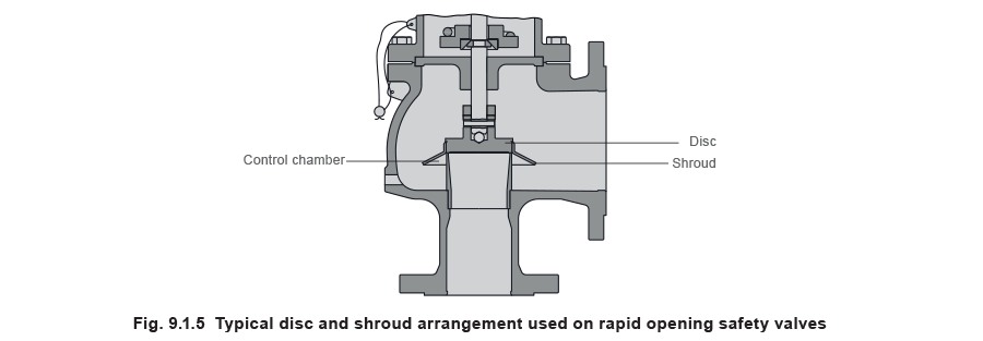
The disc is held against the nozzle seat (under normal operating conditions) by the spring, which is housed in an open or closed spring housing arrangement (or bonnet) mounted on top of the body. The discs used in rapid opening (pop type) safety valves are surrounded by a shroud, disc holder or huddling chamber which helps to produce the rapid opening characteristic.
The closing force on the disc is provided by a spring, typically made from carbon steel. The amount of compression on the spring is usually adjustable, using the spring adjuster, to alter the pressure at which the disc is lifted off its seat.
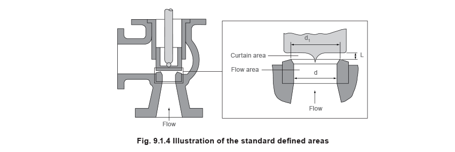
Standards that govern the design and use of safety valves generally only define the three dimensions that relate to the discharge capacity of the safety valve, namely the flow (or bore) area, the curtain area and the discharge (or orifice) area (see Figure 9.1.4).
1. Flow area – The minimum cross-sectional area between the inlet and the seat, at its narrowest point. The diameter of the flow area is represented by dimension ‘d’ in Figure 9.1.4.

2. Curtain area – The area of the cylindrical or conical discharge opening between the seating surfaces created by the lift of the disk above the seat. The diameter of the curtain area is represented by dimension ‘d1’ in Figure 9.1.4.

3. Discharge area – This is the lesser of the curtain and flow areas, which determines the flow through the valve.
Basic operation of a safety valve
Lifting
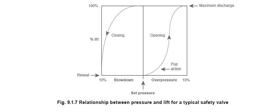
When the inlet static pressure rises above the set pressure of the safety valve, the disc will begin to lift off its seat. However, as soon as the spring starts to compress, the spring force will increase; this means that the pressure would have to continue to rise before any further lift can occur, and for there to be any significant flow through the valve.
The additional pressure rise required before the safety valve will discharge at its rated capacity is called the overpressure. The allowable overpressure depends on the standards being followed and the particular application. For compressible fluids, this is normally between 3% and 10%, and for liquids between 10% and 25%.
In order to achieve full opening from this small overpressure, the disc arrangement has to be specially designed to provide rapid opening. This is usually done by placing a shroud, skirt or hood around the disc. The volume contained within this shroud is known as the control or huddling chamber.
As lift begins (Figure 9.1.6b), and fluid enters the chamber, a larger area of the shroud is exposed to the fluid pressure. Since the magnitude of the lifting force (F) is proportional to the product of the pressure (P) and the area exposed to the fluid (A); (F = P x A), the opening force is increased.
This incremental increase in opening force overcompensates for the increase in spring force, causing rapid opening. At the same time, the shroud reverses the direction of the flow, which provides a reaction force, further enhancing the lift.
These combined effects allow the valve to achieve its designed lift within a relatively small percentage overpressure. For compressible fluids, an additional contributory factor is the rapid expansion as the fluid volume increases from a higher to a lower pressure area. This plays a major role in ensuring that the valve opens fully within the small overpressure limit. For liquids, this effect is more proportional and subsequently, the overpressure is typically greater; 25% is common.
Reseating
Once normal operating conditions have been restored, the valve is required to close again, but since the larger area of the disc is still exposed to the fluid, the valve will not close until the pressure has dropped below the original set pressure. The difference between the set pressure and this reseating pressure is known as the ‘blowdown’, and it is usually specified as a percentage of the set pressure. For compressible fluids, the blowdown is usually less than 10%, and for liquids, it can be up to 20%.
The design of the shroud must be such that it offers both rapid opening and relatively small blowdown, so that as soon as a potentially hazardous situation is reached, any overpressure is relieved, but excessive quantities of the fluid are prevented from being discharged. At the same time, it is necessary to ensure that the system pressure is reduced sufficiently to prevent immediate reopening.
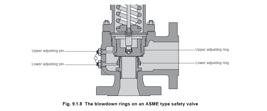
The blowdown rings found on most ASME type safety valves are used to make fine adjustments to the overpressure and blowdown values of the valves (see Figure 9.1.8). The lower blowdown (nozzle) ring is a common feature on many valves where the tighter overpressure and blowdown requirements require a more sophisticated designed solution. The upper blowdown ring is usually factory set and essentially takes out the manufacturing tolerances which affect the geometry of the huddling chamber.
The lower blowdown ring is also factory set to achieve the appropriate code performance requirements but under certain circumstances can be altered. When the lower blowdown ring is adjusted to its top position the huddling chamber volume is such that the valve will pop rapidly,
minimising the overpressure value but correspondingly requiring a greater blowdown before the valve re-seats. When the lower blowdown ring is adjusted to its lower position there is minimal restriction in the huddling chamber and a greater overpressure will be required before the valve is fully open but the blowdown value will be reduced.
For most countries, there are independent bodies who will examine the design and performance of a product range to confirm conformity with the relevant code or standard. This system of third party approval is very common for any safety related products and is often a customer requirement before purchase, or a requirement of their insurance company.
The actual requirements for approval will vary depending on the particular code or standard. In some cases, revalidation is necessary every few years, in others approval is indefinite as long as no significant design changes are made, in which case the approval authority must be notified, and re-approval sought. In the USA, the National Board of Boiler and Pressure Vessel Inspectors represents the US and Canadian government agencies empowered to assure adherence to code construction and repair of boilers and pressure vessels.
Some of the more commonly encountered bodies are listed in Table 9.1.1.
Table 9.1.1 Approval authorities
(Via https://www.spiraxsarco.com/learn-about-steam/safety-valves/safety-valves )